
Flowban Installation Instructions
Don't let Water Overflows cause Thousands in Damage
Flowban Download Installation Instructions & Tech Sheet
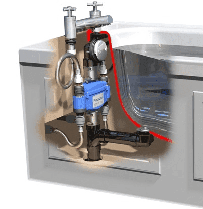
Flowban® is connected to the overflow pipe between the outlet from the tub and the waste. The hot and cold pipes are connected to the supply ports either side of the float chamber.
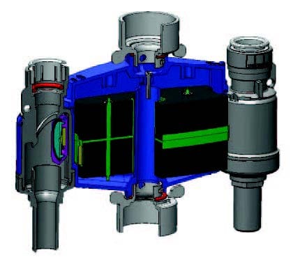
When the water level in the bath reaches the overflow outlet, water enters the central chamber and activates the float. As the float rises, the magnets that are set into each end of the float react with the magnets on the flapper valves in the supply ports. The flapper valves are pushed into the water flow where the water pressure holds them in the closed outlet.
A trickle of water is allowed to bypass the flapper valve and out of the faucet. The trickle indicates the faucet is still open, but the water level will drop and the central chamber drain. This allows the float to revert to its rest position, but the flapper valves stay closed, held in place by the water pressure.
Once the faucet is finally turned off, the pressure equalizes each side of the flapper valve which is then drawn back to the open position by the magnet on the float. The faucet can now be opened again, and full flow will resume.
Flowban Efficiency
Flowban® has only three moving parts. It uses no electricity, being entirely mechanical in operation. Resetting the system after shut off is simply intuitive. No user instructions are necessary and, if the installation is hidden by a bath panel, there is no need for anyone to know that a flood prevention device is fitted.
No Maintenance or Servicing
Under normal usage conditions Flowban® requires NO Maintenance or Servicing. However it is recommended that a bi-annual check is carried out to confirm correct functioning of the unit. If foreign matter is obstructing the movement of the float in the central chamber, then cleaning will be required but access to the chamber is very simple.
Tested to comply with IGC 241 – 2008a UPC Model # NF/FB01 ![]()
If you have any Questions, or would like Bulk Pricing please feel free to call us (702) 304-2170 or use contact form and we will get back to you.
Location
Flowban® must be installed in a location where there is access enabling it to be removed in the rare event of it needing cleaning. It must be installed in a vertical plane and be attached to either 1½” PVC or 1½” brass waste pipe.
It cannot be installed on a waste with a trip activator passing through the waste pipe. The water supply pipes are connected using John Guest push fit fittings.
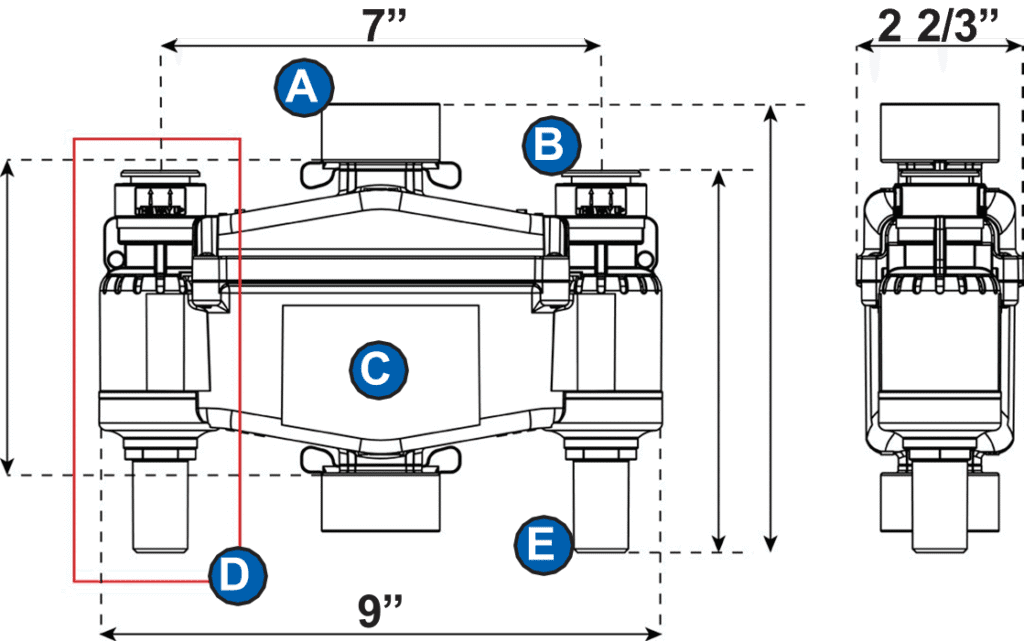
The connections to the inlets are ¾” CTS fittings and ¾” CTS inserts are required on the outlets.
The flow direction must be from bottom to top. The supply lines can be either hot or cold water or pre-mixed. In the latter case the flow should be split below the unit and reconnected above it.
If required, only one inlet may be connected. Faucets may be located anywhere on the bathtub as required.
- Maximum Static 8 Bar - 115 psi
- Maximum Working 12 Bar - 180 psi
- Minimum 1 Bar - 15 psi
- Maximum flow rate through each inlet port 18 gpm
- Water Temperature Min. 40F - Max. 158F
Recommended Plumbing Fittings or Equivalent.
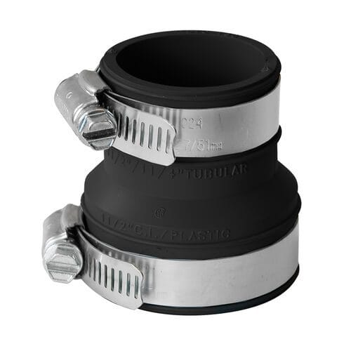
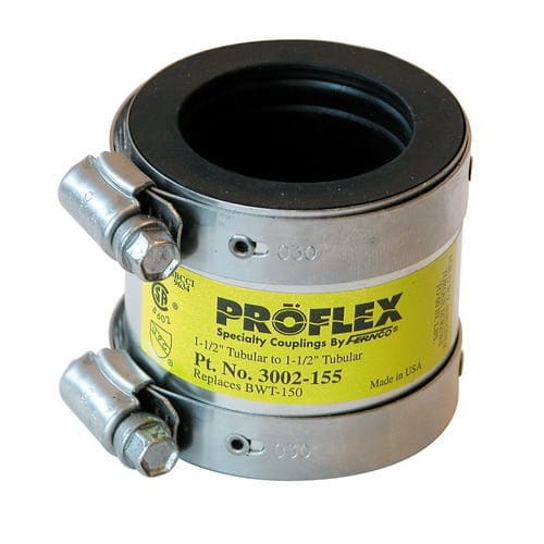
Brass/Metel Waste pipes – Fernco DTC-150. PVC/ABS Waste pipes – Fernco Proflex 3002-150 & Fernco 1056-150RC
 Flowban® is manufactured using Fortron which complies with NSF Standard 61.
Manufactured in compliance with IGC 241 – 2008a Universal Plumbing Code – Model No. NF/FB01
Certified for use with only JOHN GUEST PUSH-TO LOCK FITTINGS™ Substitutions should not be used.


Suitable waste and overflow fittings.
Flowban® cannot be installed on a waste and overflow fitting which has any kind of waste activating mechanism passing down the overflow pipe. It is not possible to use a “Snake” for cleaning the drain with Flowban® installed.
Recommendation
Bathtubs, faucets and overflows differ greatly and care must be taken to understand the individual plumbing arrangements prior to undertaking any installation. Ensure you can isolate the supply water and are familiar with work of this nature. We recommend you always use a licensed plumber to install a Flowban® unit.
Orientation
The Flowban® unit must be fitted in a vertical plane. It must not be fitted lying flat or at an angle since this will hinder operation. Directions for orientation are clearly marked on the main body of the Flowban® Stops Overflows system.
Positioning
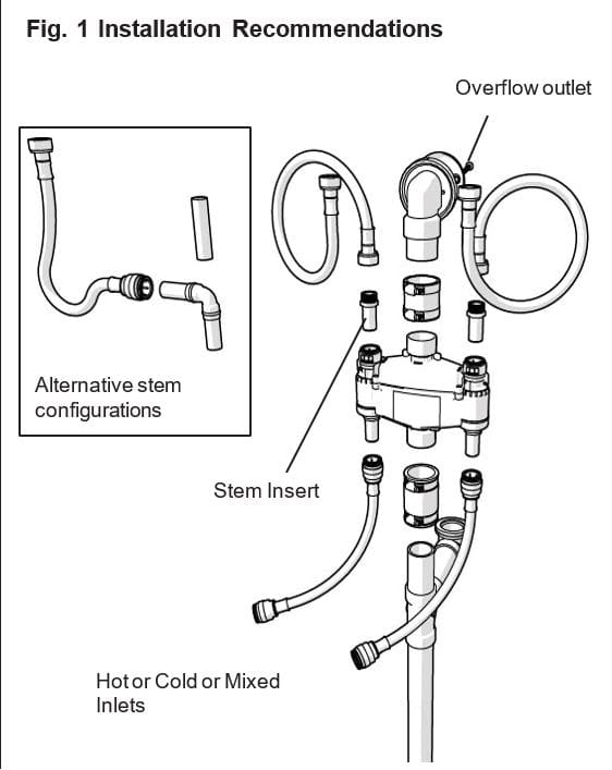
The Flowban® unit must be located between the overflow outlet (See Fig. 1) and the waste in a position as high as can be reasonably achieved. This position will allow any excess water flowing through the overflow outlet from the bath or basin to pass through the Flowban® unit causing activation of the valves to shut off the supply water. The positioning of the Flowban® unit is the same for all types of installations.
Connection to overflow pipe
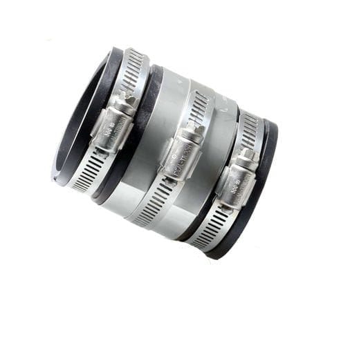
Standard Fernco or equivalent waste connectors should
be used to attach the 1 ½” coupling connector.
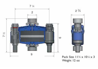
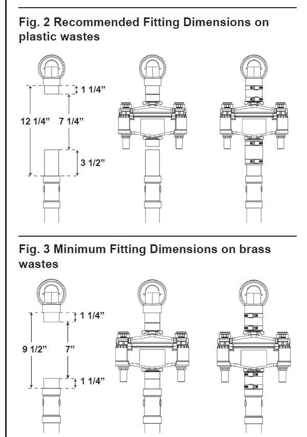
To allow for vertical movement of the coupling connector when the unit is being installed or when it is removed for servicing, we recommend minimum dimensions of the overflow pipe for both brass and plastic wastes. There should be a gap of 7 ¼” in the pipe and a minimum height of 3 ½” of pipe below the gap and 1 ¼” above the gap. (See Fig. 2)
If the overall length of 12 ¼” between the shoulders on the waste pipe cannot be achieved, then it is possible by using a brass waste to reduce the overall length to 9 ½”. Using the DTC-150 connectors which slide up or down the brass pipe, you can allow the brass pipe to slide inside the coupling connector so that the Flowban unit can be installed or removed if required.
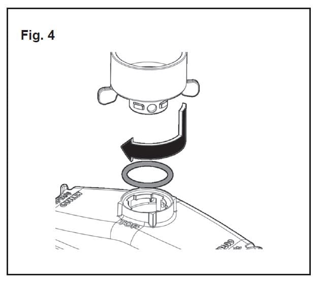
When installing the coupling connector in place make sure that the “O” ring is properly seated and take care not to apply too much force to the lugs when twisting as they can break away. When twisting the connector, the lugs must finish by lining up between the inlet ports as shown in the photograph on the front page, not across the body of the Flowban at right angles. Make sure that the connector clicks into place after a quarter turn otherwise the waste may leak.
Once the Flowban® unit is correctly installed on a rigid waste overflow pipe it will require no other form of attachment or stiffening. Ensure all fittings are watertight by looking for leaks during testing once the installation is complete.
Water supplies
The two side valves are completely independent of each other. A single side valve can be used leaving the other side valve unconnected. Either valve can be fed with hot or cold water or pre-mixed water. Pre-mixed water can be connected to a single side valve or the flow can be split to each side valve and reconnected the other side of the Flowban® unit. The faucet control can be located on the water supplies either before or after the Flowban® unit. There is considerable flexibility as to how the controls and inlet lines are configured to suit individual plumbing and faucet control scenarios. Normal hot and cold supplies. (See Fig. 1)
Purging the system
The Flowban Stops an Overflow system, once fitted will need to be purged to clear any air inside the system. This is done by allowing the faucets to flow at full rate for 1 minute, then turning them off. Repeat this procedure three times. Should the valves actuate, simply turn off the faucets, wait for five seconds then turn them on gently. Once the system is purged of air, unintended activation of the valves such as this will not occur.
Testing
Test for leaks before replacing any bath surround or cladding.
Normal Operation and Resetting
When water enters the overflow outlet the float in the central chamber rises and magnets activate the valves that shut off the flow to the faucets. A small trickle of water remains which indicates that the faucets are still open. The unit will only reset itself when the faucets are closed and there is no more water going down the overflow outlet.
Maintenance
To ensure correct operation of Flowban® you are advised to check its operation once every six months. To do this, use the water from a shower head or a hose connection directed into the overflow whilst the faucets are running.
If the float activating mechanism ever becomes clogged with soap, hair or other debris that has entered from the overflow inlet the unit must be removed and cleaned. Most debris will collect in the bottom so removing the lower pipe connector by rotating it 45 degrees counter clockwise will allow cleaning of this area.
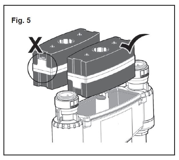
To clean the whole float chamber, remove the five screws on the top of the unit and lift out the float. After cleaning ensure that the float is replaced the correct way up (See Fig. 5) otherwise the unit will not function. Do not use abrasive cleaners. Upon reassembly care must be taken not to overtighten the screws.
5 YEAR WARRANTY
Flowban® (the device) is warranted to be Free of defective parts, material and construction for a period of five years. The device is intended for occasional use as a preventative device and should not be used as a means of automatically setting your bathtub water level on a regular basis. About Time Design Ltd (the company) and our suppliers take no responsibility for the quality of fitment of Flowban® or any loss or damage caused by defective installation. We recommend installation by a licensed plumber to ensure there are no leaks and that the device performs according to specification. The company takes no responsibility for consequential loss under any circumstances. In event of queries, in the first instance please contact us
List of Required Plumbing Fittings
The inlet water supplies should be connected to the nipples using John Guest Push-to-Lock™ fittings. The top connection is by a ¾” CTS stem into the John Guest push fit connection. The bottom connection must be made with a John Guest Push-to-Lock™ ¾” CTS connector. Suitable adapters can be used for NPT connections, either 3/4” or ½”.
For 3/4″ Plumbing Supplies
Elbows
PSEI0328E – ¾” CTS Elbow
Plug–In Elbow
PSEI222828E – Plug-In Elbow – ¾” Stem x ¾” CTS Male Connectors
PSEI012826E – ¾” x ¾” CTS x NPT Male Connector Male Connector – Lead Free Brass
MWI012826LF-E – ¾” x ¾” CTS x NPT Male Connector Brass Male Stem Adapter NPT Threads
MWI052826LF – ¾” x ¾” Stem x NPT
When making connections with rigid pipes ensure that the Flowban is not twisted or otherwise stressed which could preclude the proper operation of the internal flap valves. It may be necessary to connect to the plumbing using flexible hoses to ensure that no stresses are transmitted to the device.
Flowban® is rated at a maximum continuous hot water temperature of 158 degrees Fahrenheit at a Max. Flowrate of:
The maximum flow rate through each of the ports is 18 gallons per minute. If this rate is likely to be exceeded the flow should be restricted to stop unintentional valve actuation.
For ½” Plumbing Supplies
Reducing Coupler
PSEI202820E – Reducing Coupler – ¾” CTS x ½” CTS Reducing Elbows
PSEI212820E – Reducing Elbow – ¾” CTS x ½” CTS Reducer
PSEI062820E – Reducer – ¾” CTS x ½” CTS
Elbows
PSEI0320E – ½” CTS Elbow
Plug–In Elbow
PSEI222828E – Plug-In Elbow – ¾” Stem x ¾” CTS
To be used with:
Plug in Reducer
PSEI062820E – Reducer – ¾” Stem x ½” CTS Male Connectors
PSEI012824E – ¾” x ½” CTS x NPT Male Connector Male Connector – Lead Free Brass
MWI012824LF-E – ¾” x ½” CTS x NPT Male Connector”
Download Pdf Instructions & Parts List
8:00am - 4:00pm
Saturday & Sunday – CLOSED